Thursday, November 9, 2017
Thursday, October 19, 2017
Tuesday, October 17, 2017
Friday, November 4, 2016
Bluetooth HC-05 Interfacing With Microcontroller
HC-05 is a Bluetooth module that is mostly use in Embedded Electronics for the purpose of transfer serial data wirelessly to a Android, Laptop and also Microcontroller to Microcontroller. So we can say Bluetooth is a wireless replacement of Serial Communication. HC-05 Module (fig. 1) have 6-pin.
 |
| Front View of HC-05 |
 |
| Back View of HC-05 |
fig. 1
Pin Description:
- State - State pin is high if device is connected to another device
- RxD - Receiver Pin of Bluetooth (max 3.3V)
- TxD - Transmitter pin of Bluetooth
- GND - Ground Supply
- Vcc - +5V Supply
- EN - This pin is use to change mode(AT Command, Communication mode)
Note. Basically HC-05 work at 3.3 V but there is no problem to use this module at 5V. But the Tx & Rx pin are at 3.3V level. so DON'T CONNECT Tx Rx pin Directly to Microcontroller Drive at 5V. So use a voltage divider to convert 5V in to 3.3V level. (fig.2)
 |
| Fig.2 Voltage Divider Circuit use to convert Voltage level |
here we can also use resistance of same value.
 |
| fig.3 connection |
Wednesday, September 28, 2016
Speed Control of DC motor using Microcontroller and motor driver L293
Using Microcontroller we can easily control or interface a DC motor with direction control. but if we wants to control the speed of a DC motor. in DC we are use PWM technique to control average power delivered to load. so also here we use PWM technique to control speed o a DC motor. in motor driver L293 first & ninth pin are enable pin.
the first pin EN1 is use to enable IN1 & IN2 pin to get input and same as EN2 is use to enable IN3 & IN4 pin. if we simple drive a DC motor we connect these both pin to +5V applied at 16th pin
of L293.but to control speed of DC motor we are connect these both pin to PWM pins of Microcontroller.then we can simple control the speed of DC motor by control the Duty cycle.
 |
| L293D pin diagram |
the first pin EN1 is use to enable IN1 & IN2 pin to get input and same as EN2 is use to enable IN3 & IN4 pin. if we simple drive a DC motor we connect these both pin to +5V applied at 16th pin
of L293.but to control speed of DC motor we are connect these both pin to PWM pins of Microcontroller.then we can simple control the speed of DC motor by control the Duty cycle.
Saturday, September 10, 2016
IR Module
IR Module is a module which is use to detect obstacle.An IR module uses a comprator. which is use to compare the output of photodiode with output of preset. when output of photo diode is greater than the voltage applied at non-inverting pin of comparator, the output of comparator is goes to high. but if output of photo diode is not exceed the output of preset then the output of comparator is zero volt.
The output of photo diode is changes with change in intensity of incoming ir Light coming from IR LED. ir light is reached at photo diode after reflection by object placed in front of ir module.
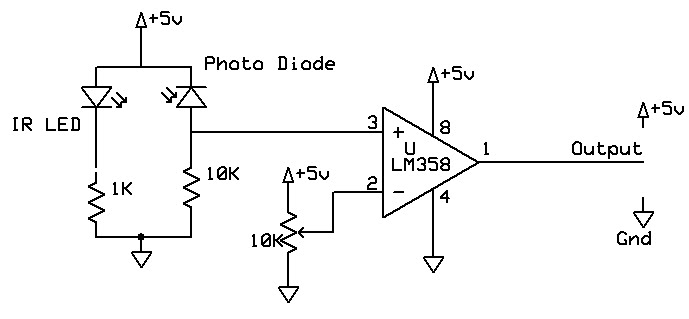 |
| Circuit of IR Module |
so we can change range of ir module by change in voltage applied at non-inverting pin.
Saturday, September 3, 2016
Speed Control of Stepper Motor using PIC microcontroller
To control the
speed of unipolar stepper motor we use a Microcontroller to control the
activation and also control activation time. ULN2003 is used as current amplifier. Preset use to control speed of motor
 |
| Circuit to speed control of stepper motor |
 |
| connection of stepper motor |
1 - coil 1
2 - coil 2
3 - coil 3
4 - coil 4
&
5 - CMN
CODE:-
unsigned short i,k;                            // Globle variable initialisation

void delay(unsigned short j)                                   // Delay function
{
 for(i=0;i<=j;i++)                        // For loop to generate multiple delay
 {
  delay_ms(1);                                                      // delay 1ms
 }
}

void main()                                                     // Main function
{
 ANSEL = 0x00;                                      // Analog selection register
 TRISA = 0x07;                                // Input/output selection register
 TRISC = 0x00;                                // Input/output selection register
 PORTC = 0x00;                                  // Default PORTC all output zero

 a = 0;                                                        // bit a is clear

 ADC_Init();                                                   // initialise ADC

 while(1)                                                            // Inf loop
 {
  k = 20 - ADC_Read(0)/60;   // Formula to generat delay by read ADC at analog 0

  PORTC=0x01;                       //
  delay(k);                         //
  PORTC=0x04;                       //
Delay(k); // PORTC=0x02; //
Delay(k); //
PORTC=0x08; //
Delay(k); //
}
}
Subscribe to:
Posts (Atom)